Yaskawa AC Drive Z1000 Bypass Technical Manual Manual do Utilizador Página 95
- Página / 462
- Índice
- RESOLUÇÃO DE PROBLEMAS
- MARCADORES
- YASKAWA AC Drive Z1000 1
- Table of Contents 3
- Preface & General Safety 13
- Product Description 14
- Applicable Documentation 14
- Terms and Abbreviations 15
- Trademarks 15
- Safety Messages 17
- WARNING 17
- Sudden Movement Hazard 17
- Electrical Shock Hazard 17
- Fire Hazard 17
- Selection 18
- Installation 18
- Settings 18
- Motor Application Precautions 19
- Drive Label Warning Example 20
- Bypass Label Warning Example 21
- Warning Label A 22
- (inside enclosure) 22
- Warning Label B 22
- Warranty Information 23
- Receiving 25
- 1.1 Section Safety 26
- Drive Nameplate 28
- Z1B 1 B 29
- 040 P T 29
- Bypass Enclosures 30
- Bypass Product Options 30
- Bypass Front Control Panel 31
- Overload Relay 32
- Control Power Transformer 32
- Drive/Bypass Logic Interlocks 32
- 208 Vac Z1B1D088 to D169 34
- 480 Vac Z1B1B096 to B180 34
- 1.5 Bypass Component Names 36
- Mechanical Installation 37
- 2.1 Section Safety 38
- 2.2 Mechanical Installation 40
- 208 Vac (Z1B1D002 to D074) 43
- 480 Vac (Z1B1B001 to B077) 43
- Electrical Installation 49
- 3.1 Section Safety 50
- 3.3 Main Circuit Wiring 56
- Ground Wiring 64
- 3.5 Control Circuit Wiring 70
- +V AC A1 A2 FM AMAC 71
- Bypass Analog Outputs 72
- Serial Communications 72
- Top Protective Cover 80
- 3.7 External Interlock 86
- 4.1 Section Safety 90
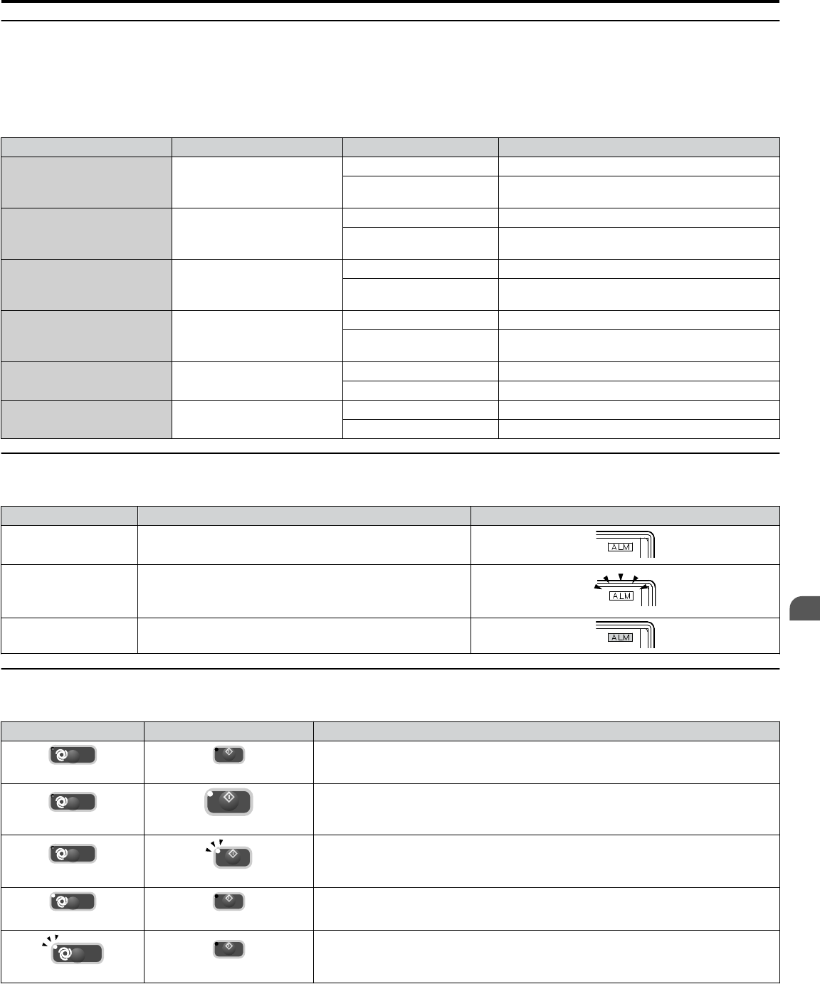
- HOA Keypad Keys and Displays 92
- LCD Display 93
- <2> 94
- 4.2 Using the HOA Keypad 96
- UB-01= 10.6A 98
- U1-02= 10000111 98
- U1-03= 01001100 98
- Entry Accepted 100
- Start-Up Programming 101
- & Operation 101
- 4.5 Start-Up Procedure 104
- 4.6 Application Selection 108
- Auto-Tuning Operation Example 112
- T1-03: Motor Rated Voltage 114
- Starting Auto-Tuning 114
- T1-02: Motor Rated Power 114
- This Page Intentionally Blank 116
- Programming 117
- 5.1 A: Initialization 118
- DC Injection brake time 120
- Max. output frequency (E1-04) 120
- Waits for twice 122
- Speed Search Activation 124
- P Control 128
- I Control 128
- PI Operation 128
- Using PI Control 128
- PI Setpoint Input Methods 128
- PI Block Diagram 130
- PI Feedback Loss Detection 132
- PI Sleep/Snooze 134
- 5.2 b: Application 138
- C4: Torque Compensation 140
- C6: Carrier Frequency 140
- <1> 141
- 5.5 d: Reference Settings 142
- V/f Pattern Settings E1-05 148
- 5.7 F: Options 150
- Setting 13: Reverse Jog 152
- 5.8 H: Terminal Functions 154
- Setting 6: Drive Ready 156
- 5.9 L: Protection Functions 168
- L3: Stall Prevention 170
- <1> <1> 172
- L3-25 = 173
- Machine Inertia 173
- Motor Inertia 173
- L5: Fault Restart 174
- L6: Torque Detection 176
- 5.12 S: Special Parameters 186
- Sequence Timer Example 2 190
- 5.14 U: Monitor Parameters 194
- Z1-07: Speed Reference Select 196
- 5.15 Z: Bypass Parameters 200
- <1> 202
- Z1-52: Bypass Phase Rotation 206
- Bypass during a trial run 217
- 6.1 Section Safety 218
- Diagnostics & 219
- Troubleshooting 219
- Fine-Tuning V/f Control 220
- Alarm and Error Displays 222
- 6.4 Fault Detection 224
- 6.5 Alarm Detection 240
- 6.6 Programming Errors 246
- Fault Reset Methods 252
- Run Command 254
- PI Output Fault 258
- Braking) 258
- Sound from Motor 258
- 7.1 Section Safety 262
- Periodic Inspection & 263
- Maintenance 263
- 7.2 Inspection 264
- Table 7.5 Maintenance Alarms 268
- 7.5 Drive Cooling Fans 272
- Appendix: A 295
- A.1 Power Ratings 296
- Specifications 297
- A.2 Drive Specifications 300
- A.3 Drive Watt Loss Data 302
- A.4 Drive Derating Data 304
- Appendix: B 307
- B.1 Parameter Groups 308
- Parameter List 309
- B.3 b: Application 310
- SCrv Acc @ Start 314
- SCrv Acc @ End 314
- Torq Comp Gain 314
- B.5 d: References 316
- EF0 Detection 318
- EF0 Action 318
- M1-M2 Func Sel 320
- M3/M4 Func Sel 320
- M5/M6 Func Sel 320
- B.9 L: Protection Function 324
- L8: Drive Protection 326
- FanElapsTimeCnt 329
- B.12 S: Special Application 330
- T: Motor Tuning 332
- Mtr Iron Loss(W) 333
- B.13 U: Monitors 334
- 00000000 336
- U3: Fault History 338
- U4: Maintenance Monitors 340
- B.14 Z: Bypass Parameters 344
- PL Brownout T 345
- B.15 Defaults by Drive Model 352
- Appendix: C 355
- C.1 BACnet Configuration 356
- Communications 357
- C.3 Connecting to a Network 358
- C.4 BACnet Setup Parameters 360
- Controlling the Bypass 362
- Analog Input Objects 364
- Analog Output Objects 364
- Analog Value Objects 364
- Binary Output Objects 366
- Binary Value Objects 366
- Device Object 368
- Enter Command Types 370
- Appendix: D 375
- Master (PLC or other) 376
- MEMOBUS/Modbus 377
- D.3 Connecting to a Network 378
- D.7 Message Format 384
- D 1 4 0 385
- (Lower) (Upper) 385
- D.8 Message Examples 386
- D.9 MEMOBUS/Modbus Data Table 388
- Broadcast Messages 398
- Fault Trace Contents 398
- Bypass Fault Codes 400
- Alarm Register Contents 400
- D.11 Communication Errors 402
- Appendix: E 403
- E.1 APOGEE FLN Set-Up 404
- Apogee FLN Network 405
- Protocol 405
- Network Termination 406
- Recommended Cable 406
- Other Functionality 408
- Stop with Fault (FB14) 414
- E.7 Fault Codes 416
- Appendix: F 419
- Metasys Field 420
- Controller 420
- Metasys N2 Network 421
- Reading and Resetting Faults 426
- Metasys N2 I/O 426
- F.4 Bypass Operations by N2 428
- F.6 Metasys N2 Point Database 430
- Appendix: G 435
- G.1 Section Safety 436
- Standards Compliance 437
- G.2 European Standards 438
- Appendix: H 441
- Z1000 Bypass Specifications 442
- Motor Specifications 442
- Quick Reference Sheet 443
- Monitor Outputs 444
- H.3 User Setting Table 446
- Numerics 451
- Revision History 460
- YASKAWA AC Drive Z1000 Bypass 462
Manuais e produtos relacionados com Equipamento Yaskawa AC Drive Z1000 Bypass Technical Manual
 (305 páginas)
(145 páginas)
(329 páginas)
(391 páginas)
(357 páginas)
(226 páginas)
(114 páginas)
(434 páginas)
(390 páginas)
(68 páginas)
(52 páginas)
(292 páginas)
(39 páginas)
(373 páginas)
(305 páginas)
(145 páginas)
(329 páginas)
(391 páginas)
(357 páginas)
(226 páginas)
(114 páginas)
(434 páginas)
(390 páginas)
(68 páginas)
(52 páginas)
(292 páginas)
(39 páginas)
(373 páginas)
© 2020, manymanuals-pt.com. Todos os direitos reservados. | 0.035 s |
 Manymanuals.com
 Manymanuals.de
 Manymanuals.fr
 Manymanuals.it
 Manymanuals.pl
 Manymanuals.cz
 Manymanuals.es
 Manymanuals-pt.com
Comentários a estes Manuais